Plucked String Digital Waveguide
Moving the Pluck Position
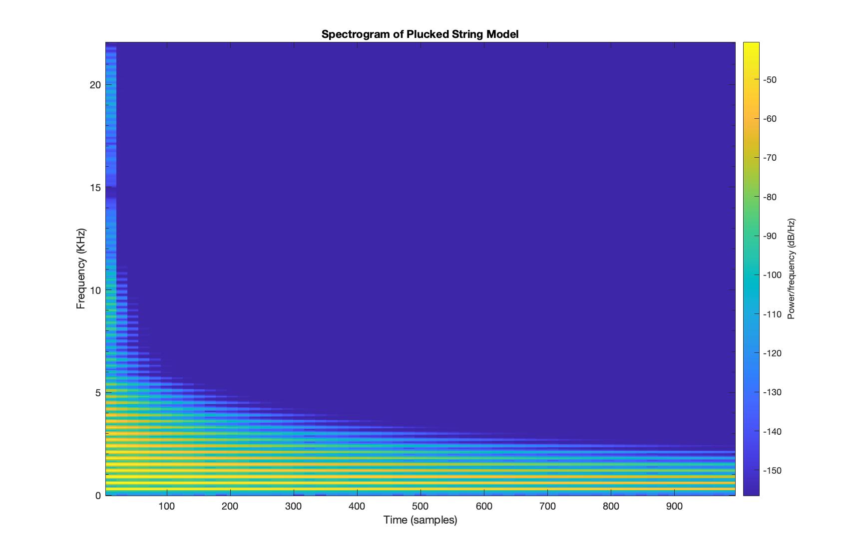
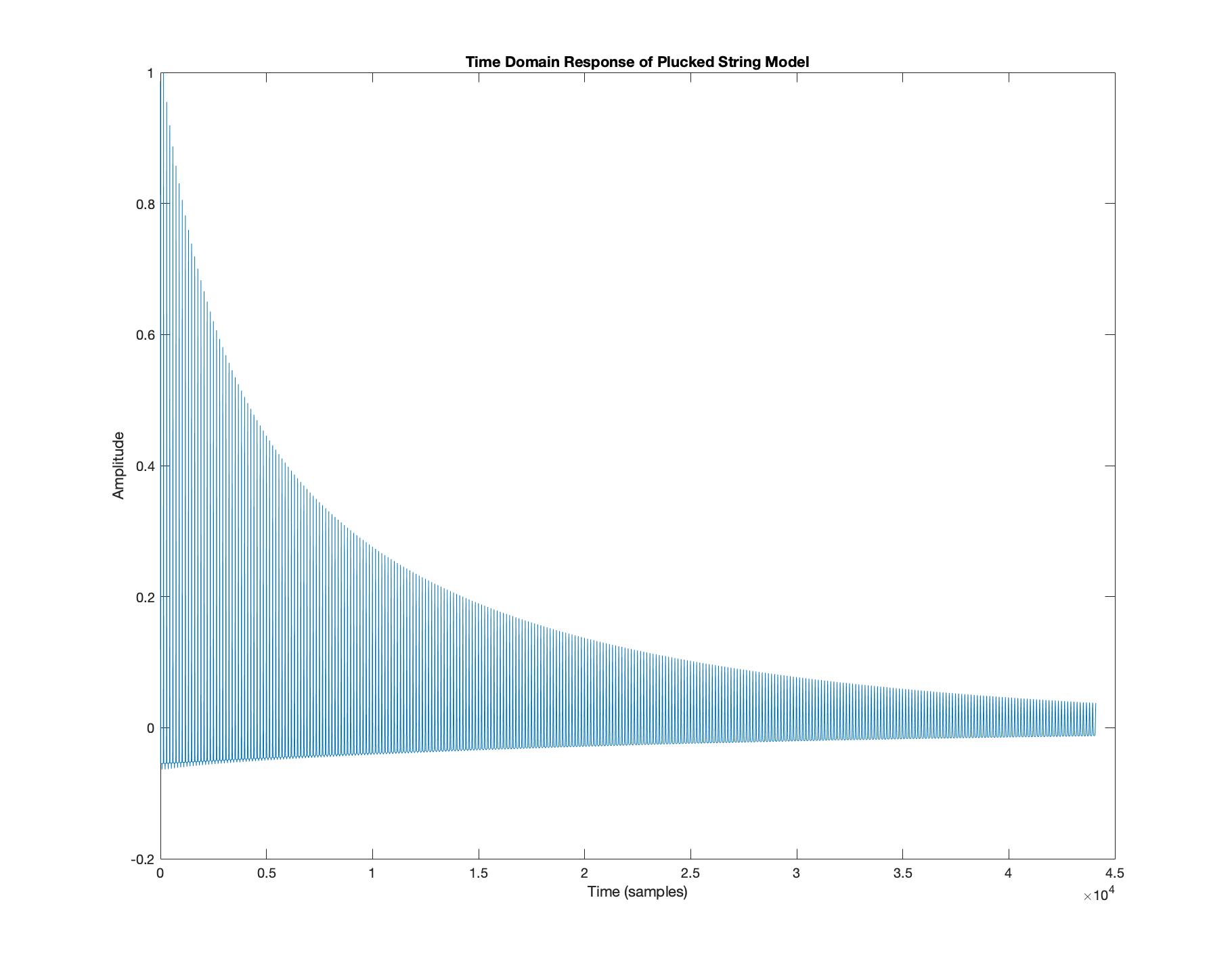
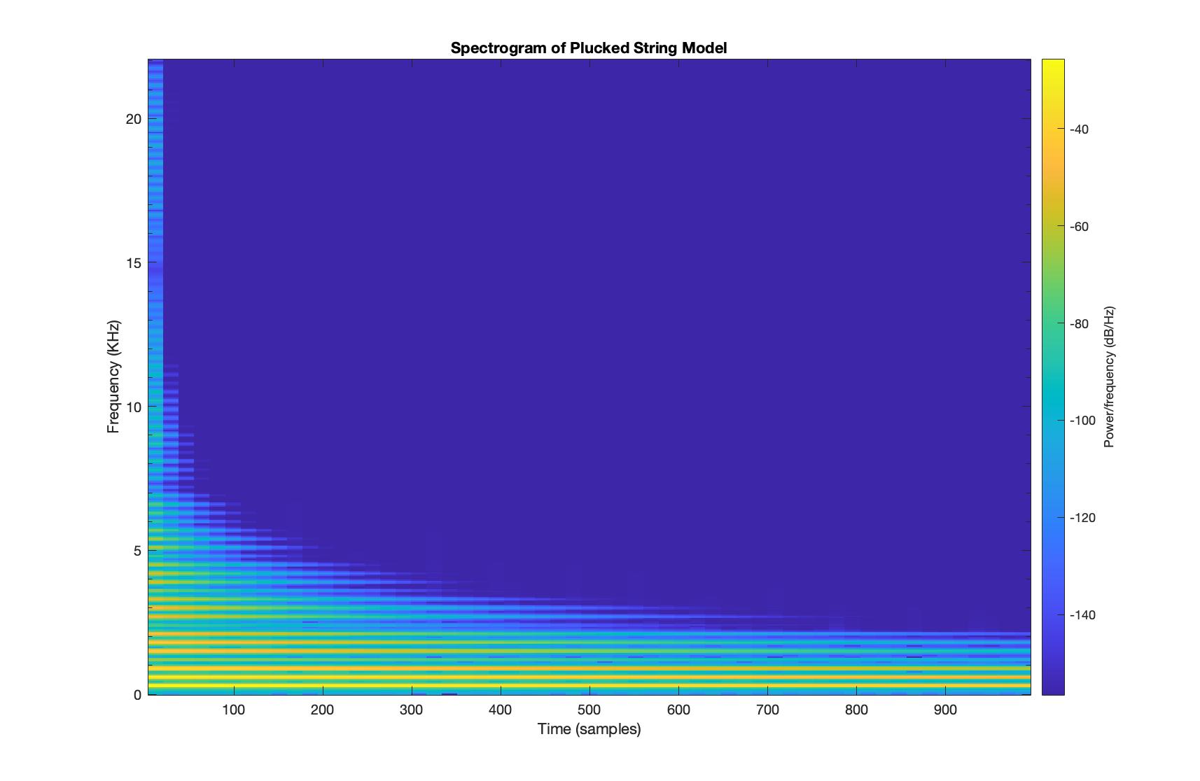
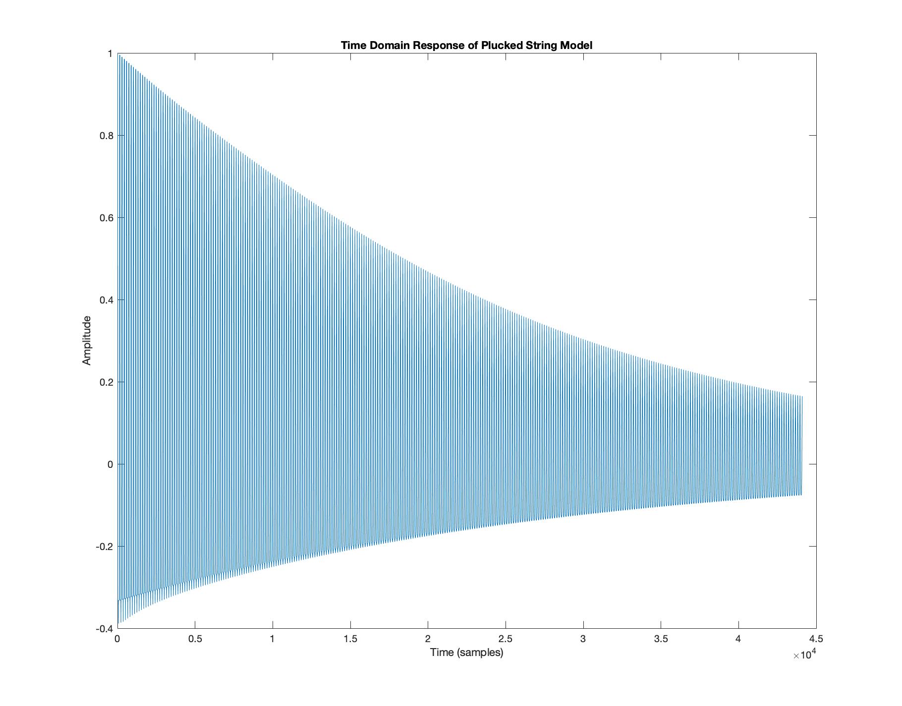
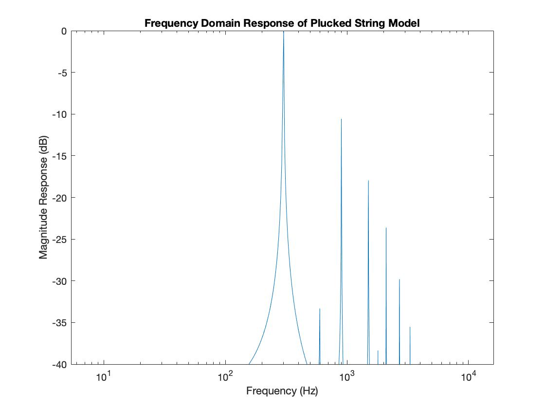
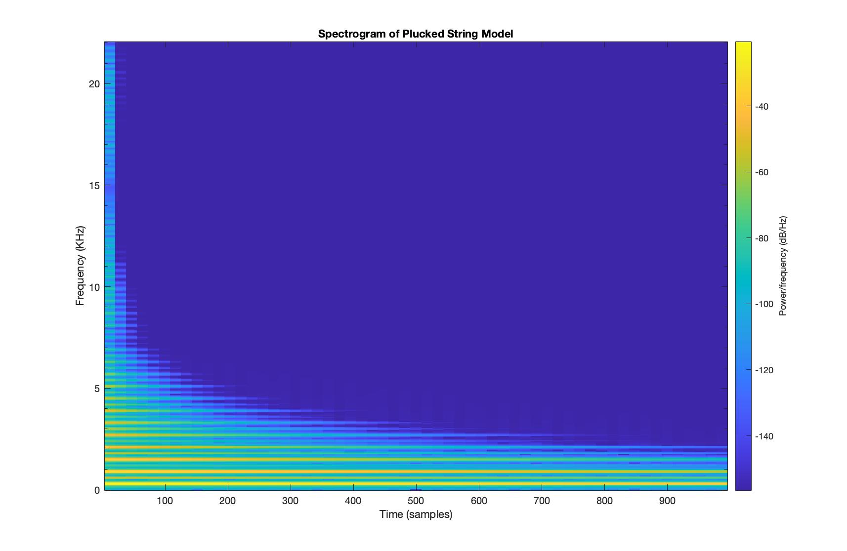
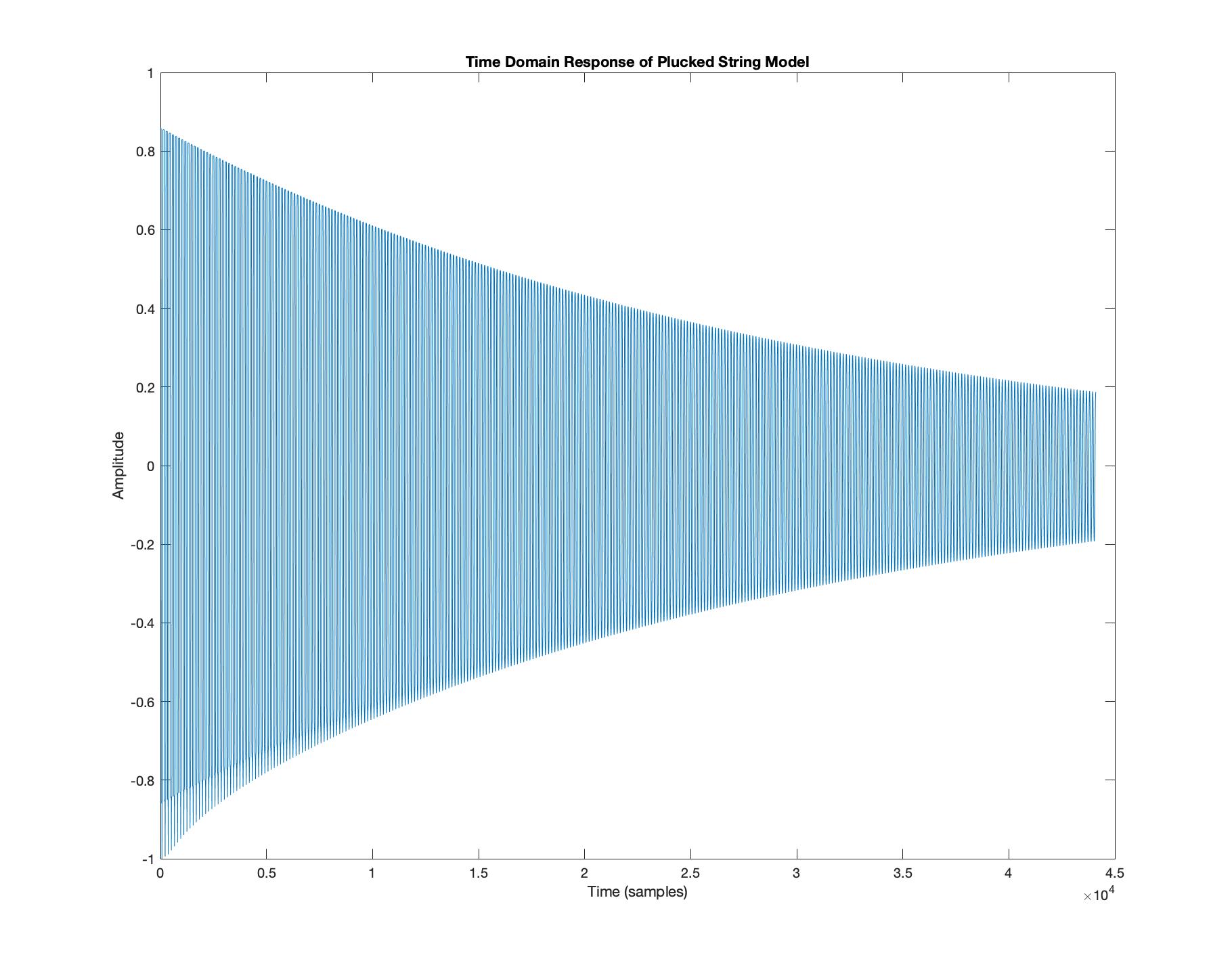
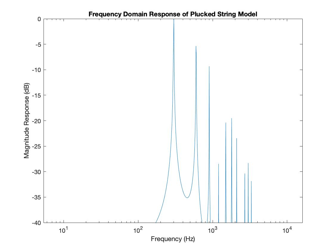
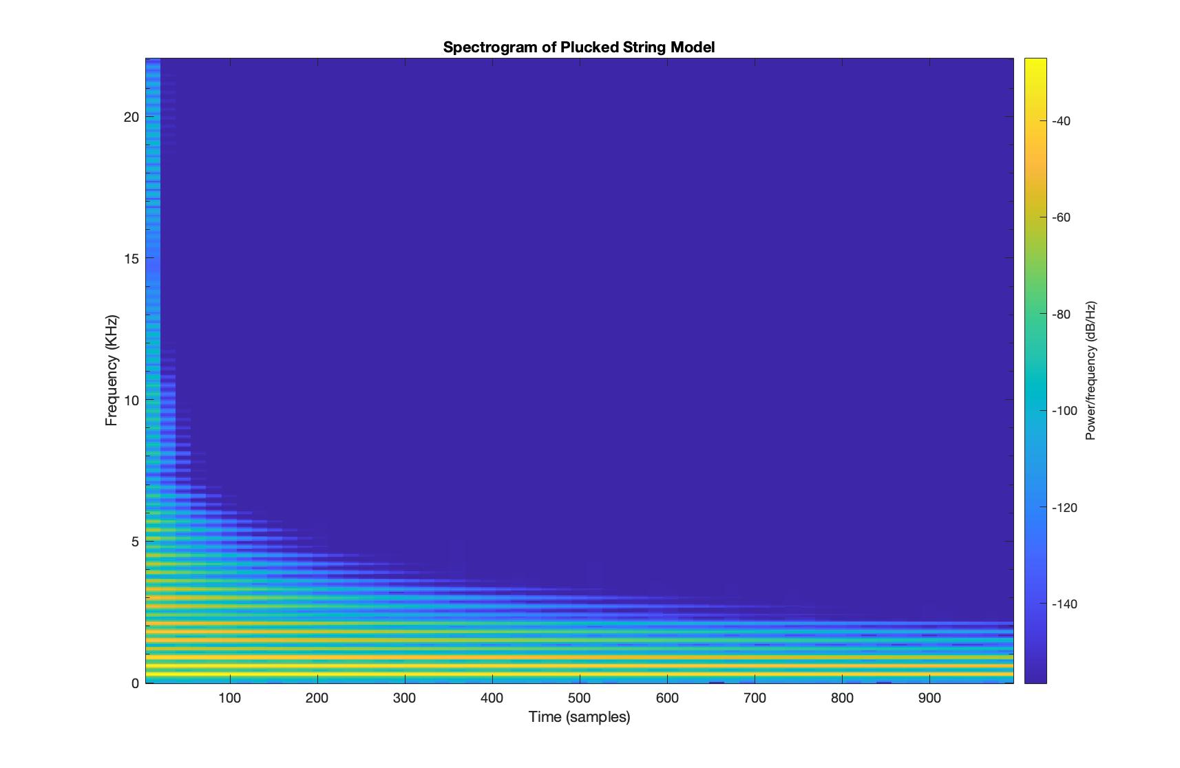
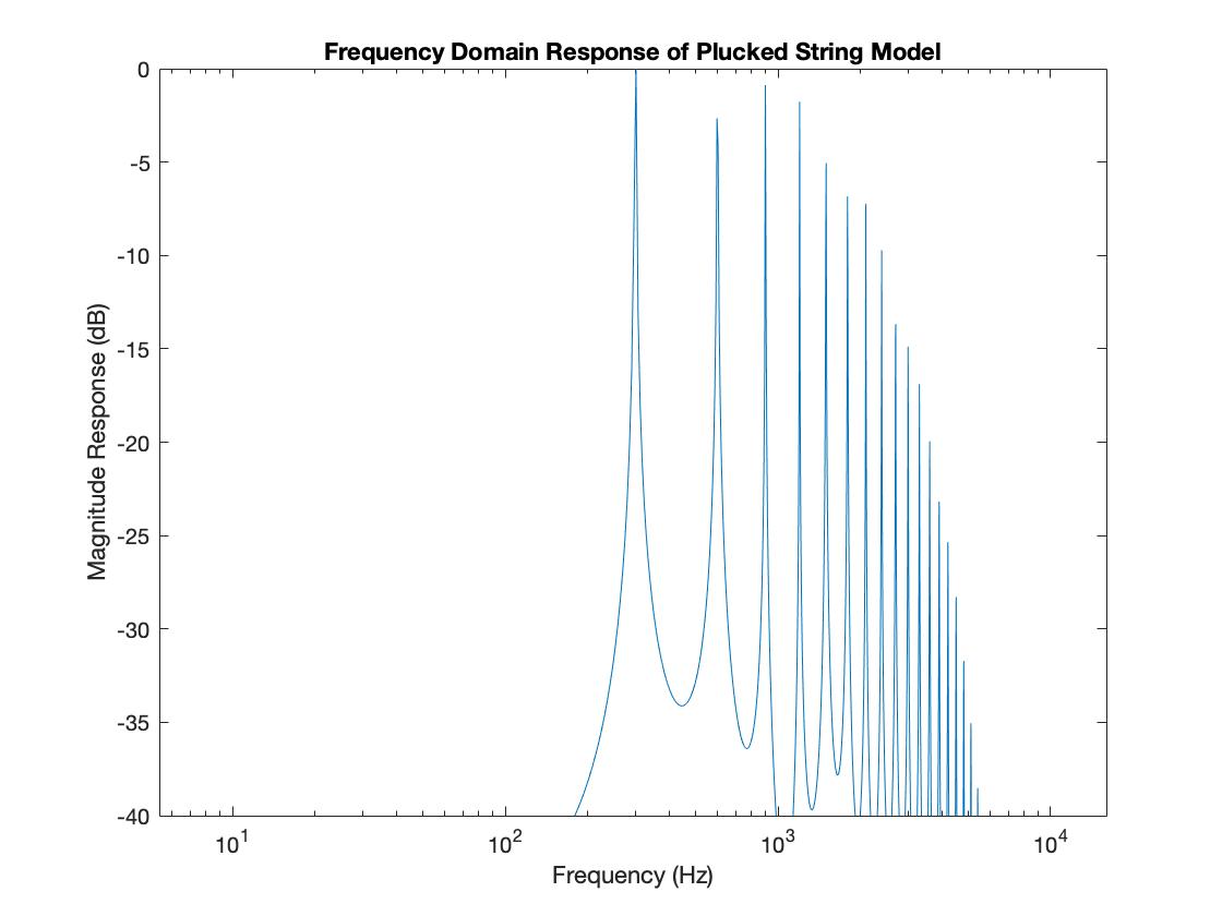
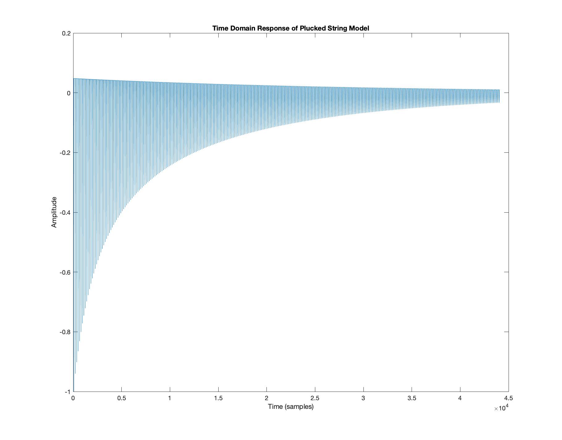
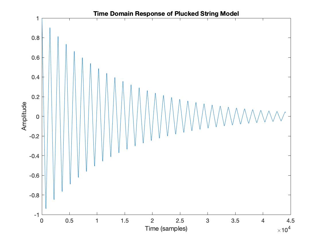
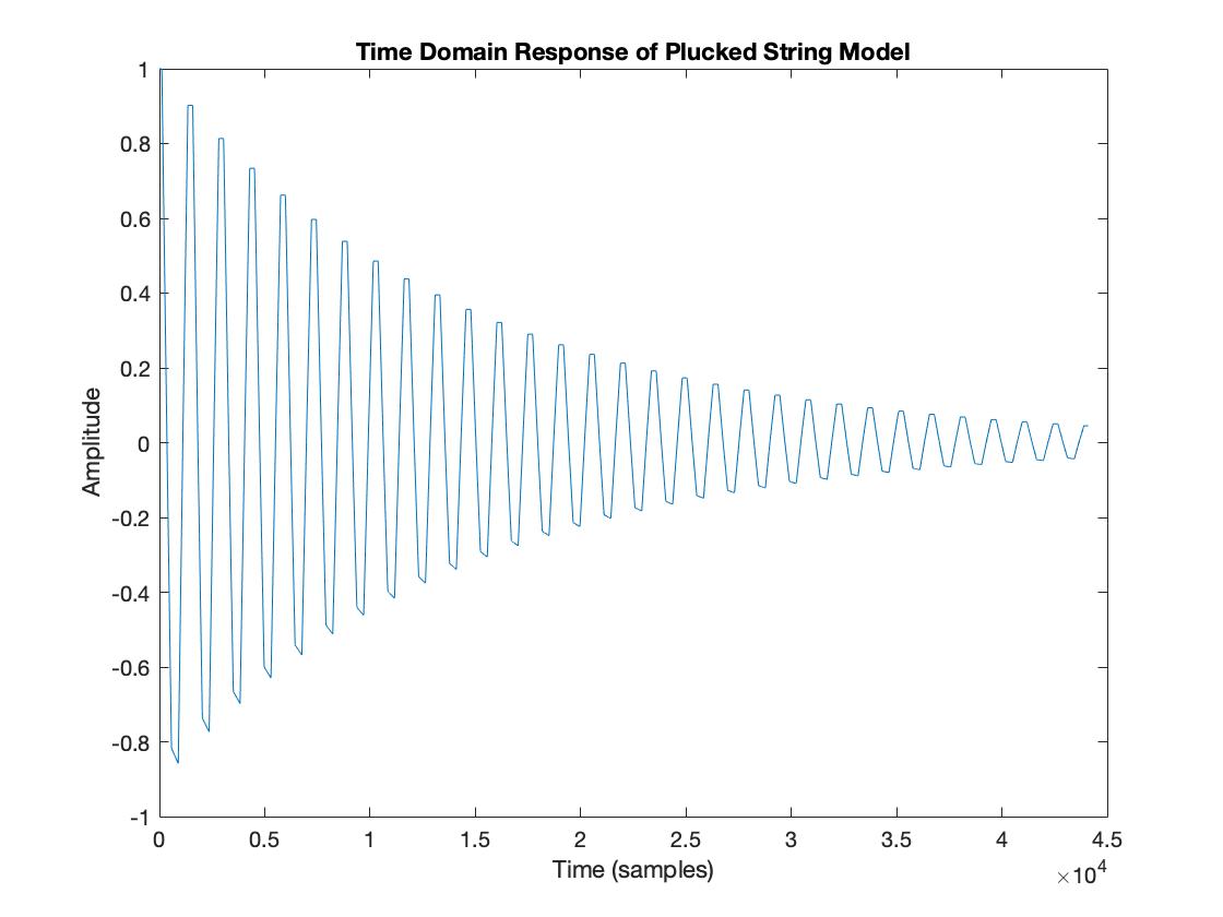
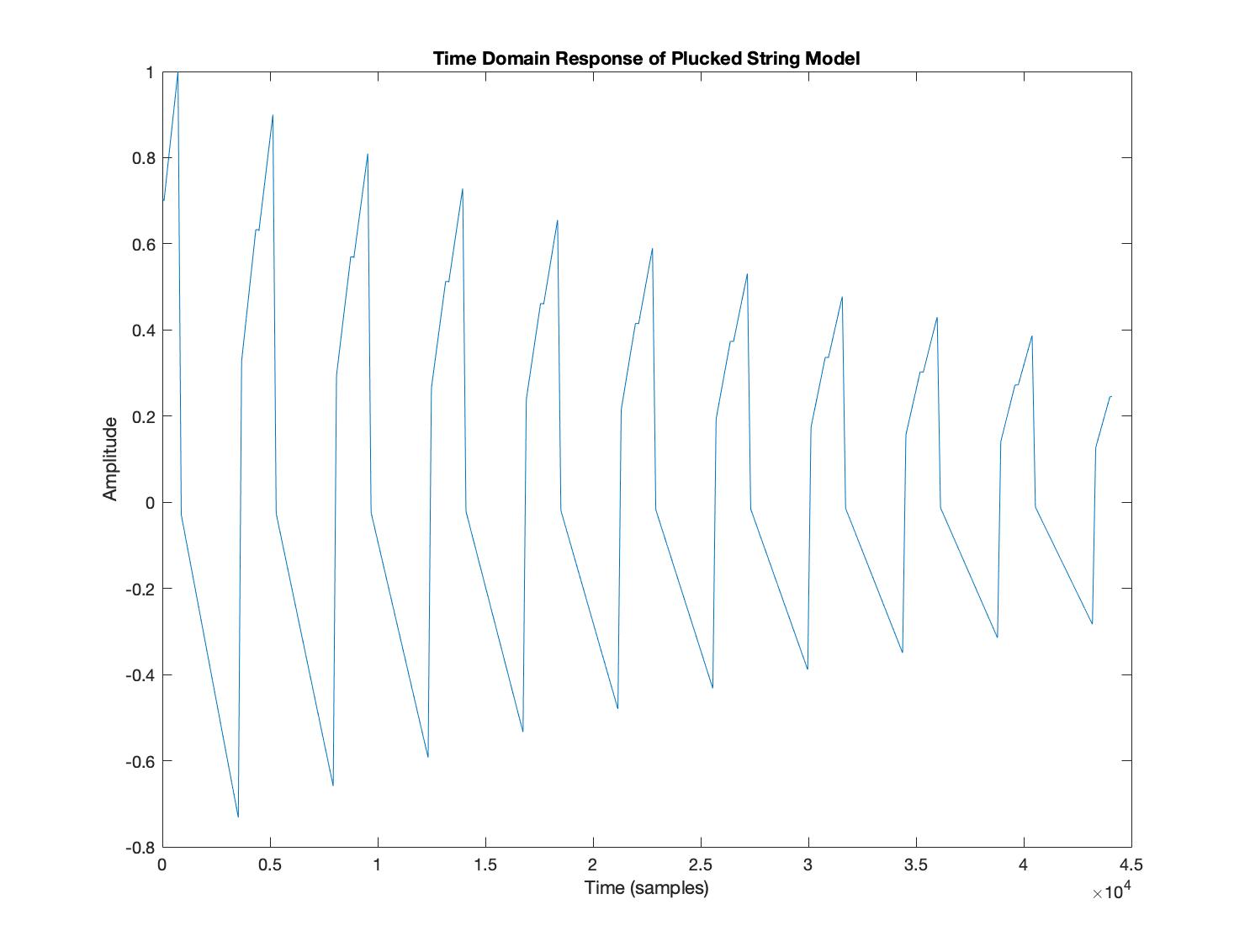
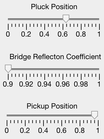
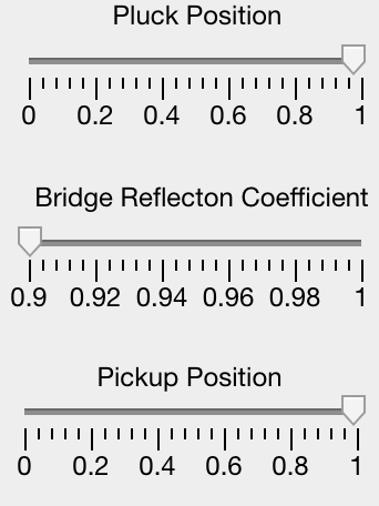
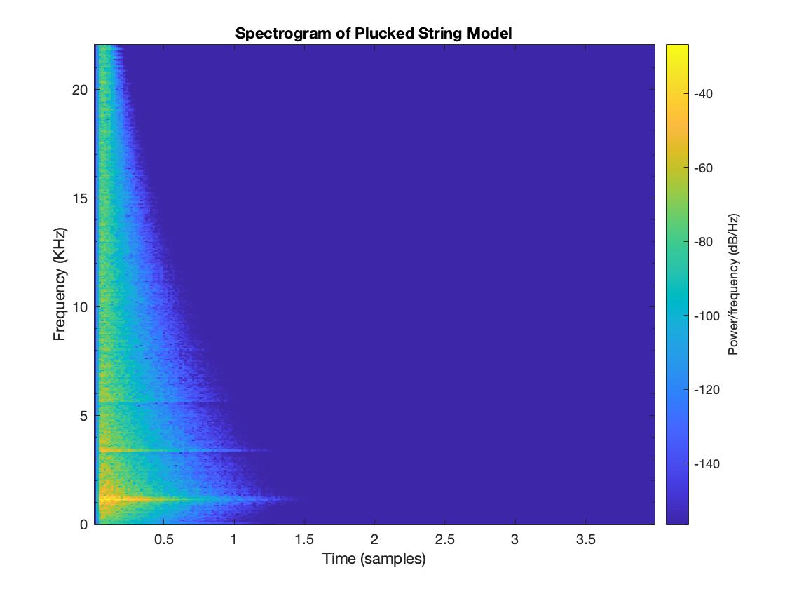
We can explore timbres created by the string digital waveguide by setting both the pickup and pluck position at 5% along the string. Then slowly moving the puck position along, a range of slightly different sounds are generated. A fundamental of 294 Hz (Approx. D4) was used.
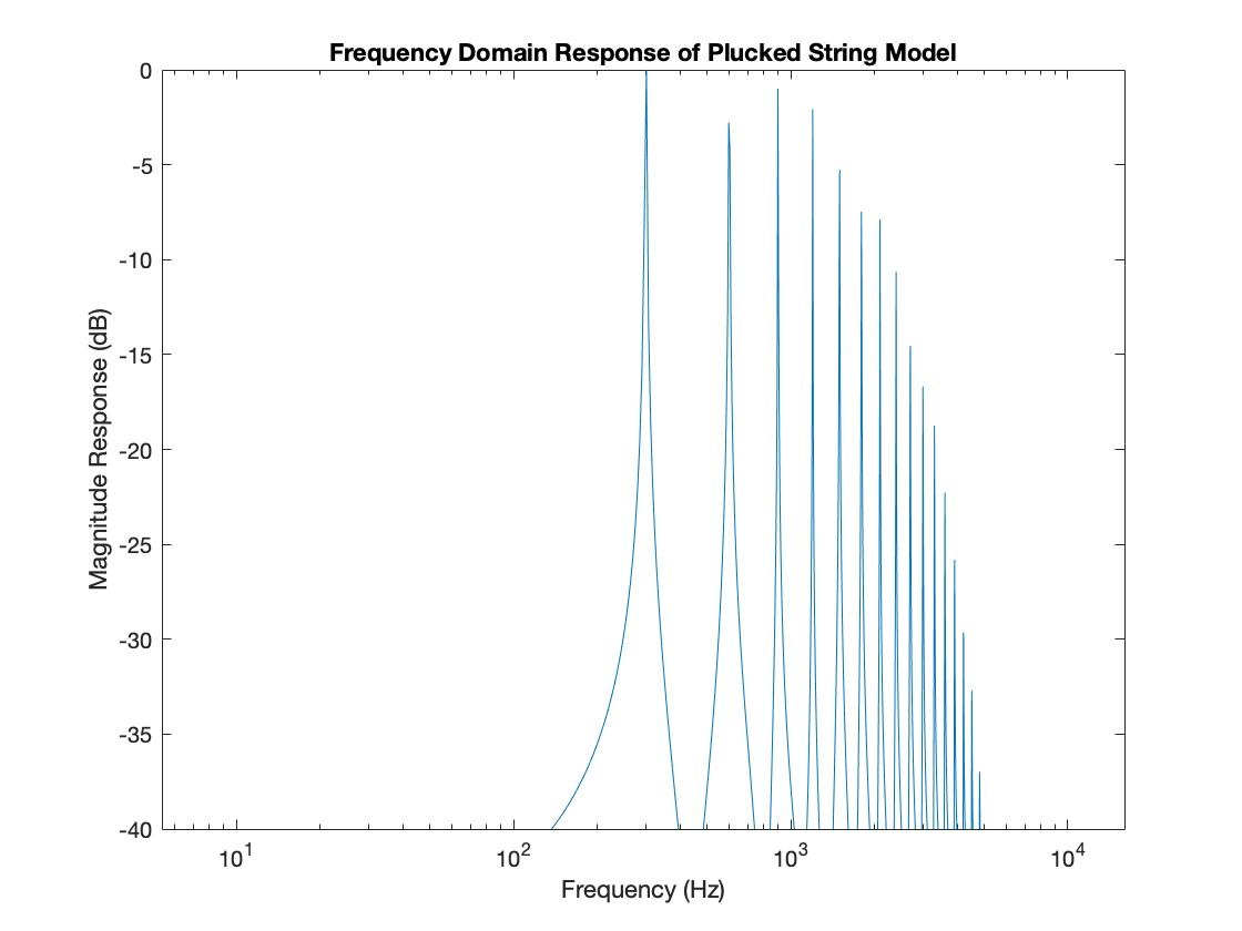
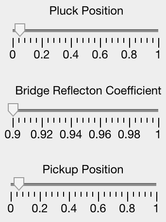
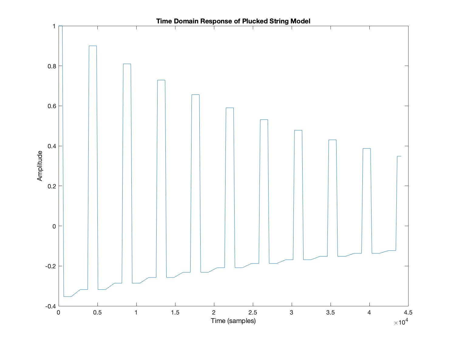
Pluck Position at 5%
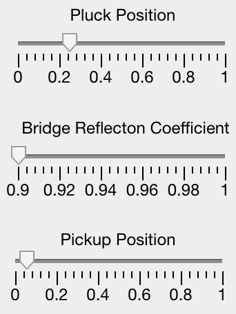
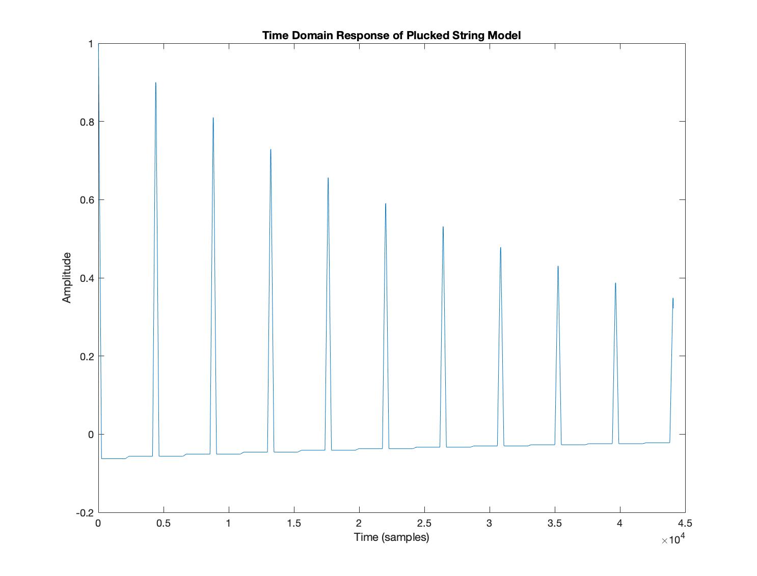
Pluck Position at 25%
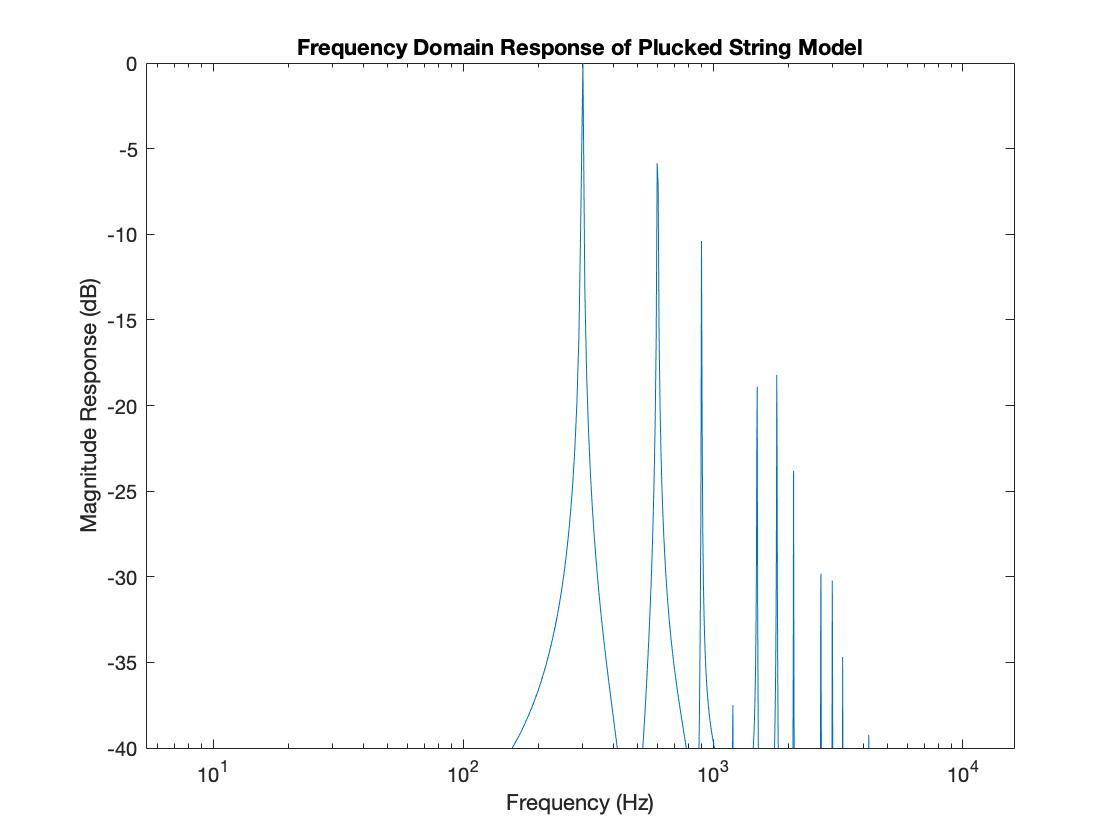
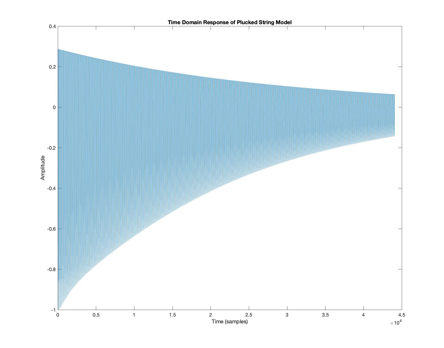
Pluck Position at 50%
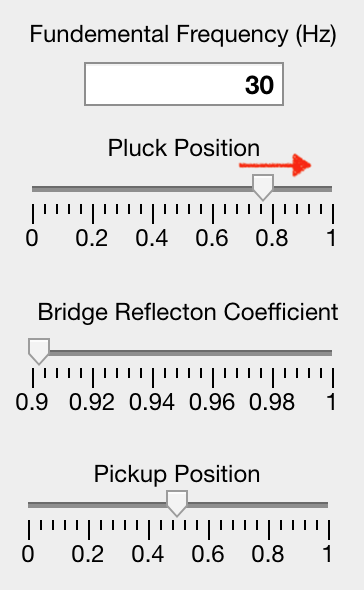
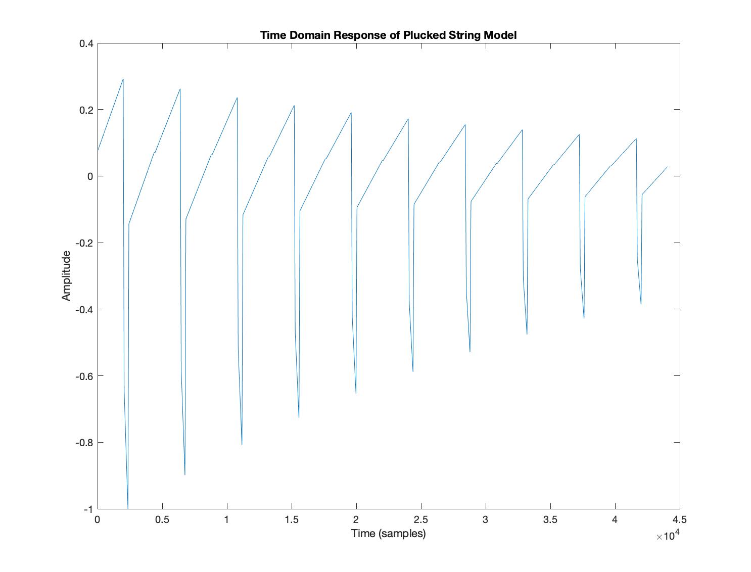
Pluck Position at 75%

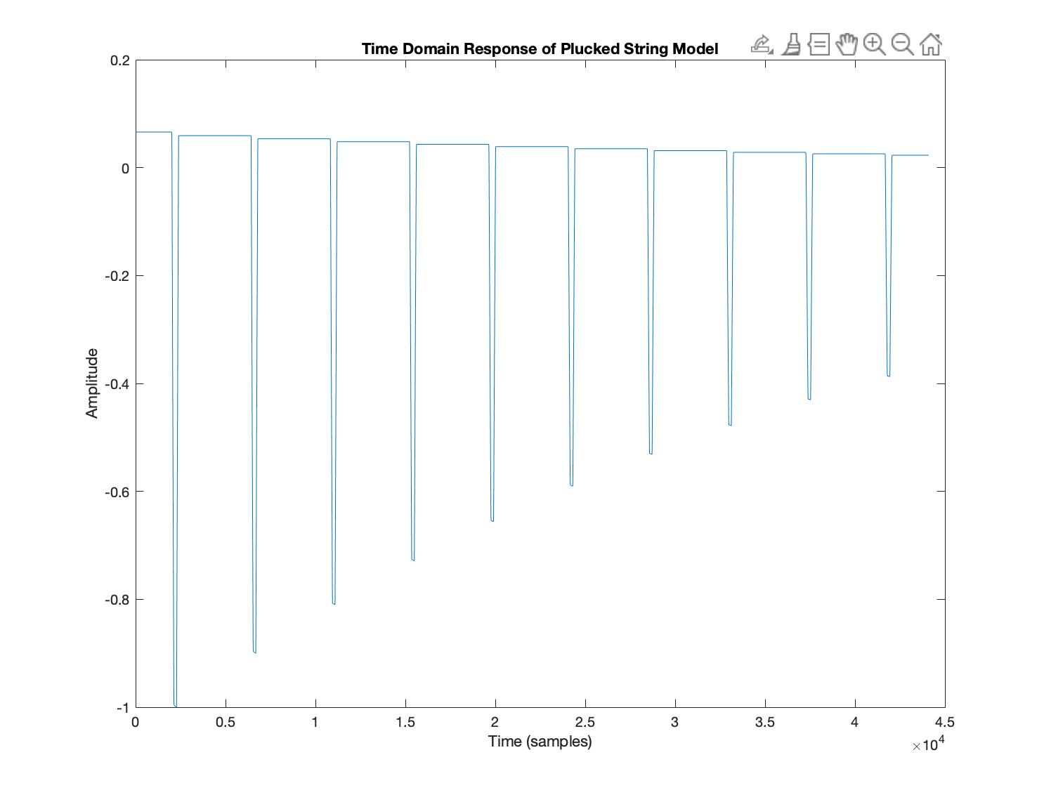
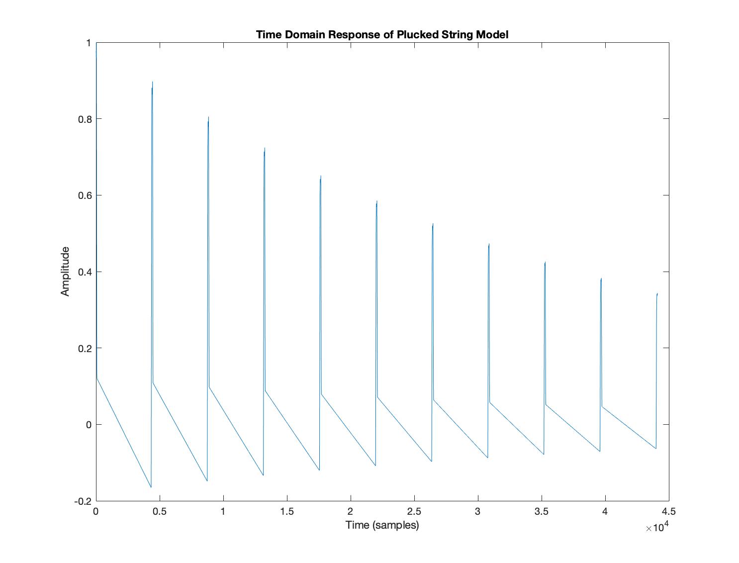
Pluck Position at 95%
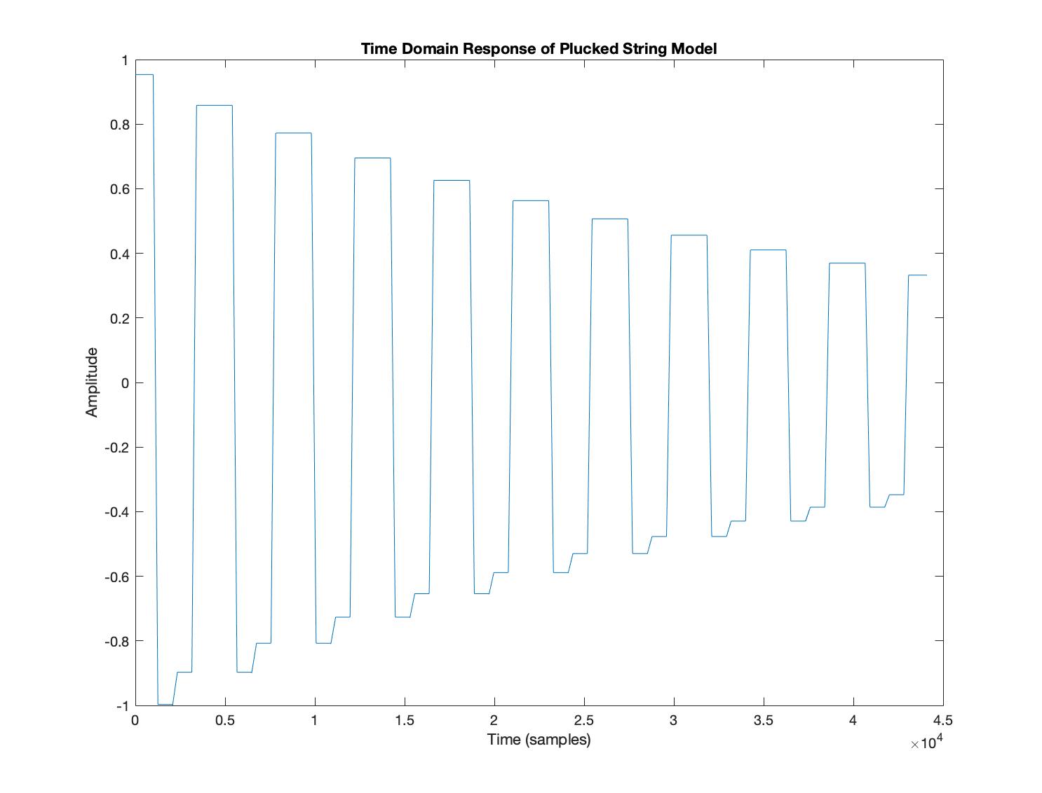
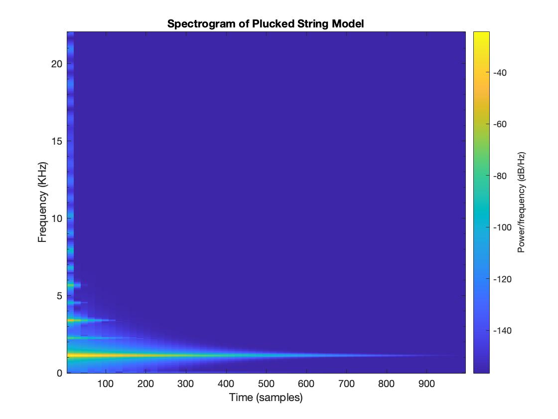
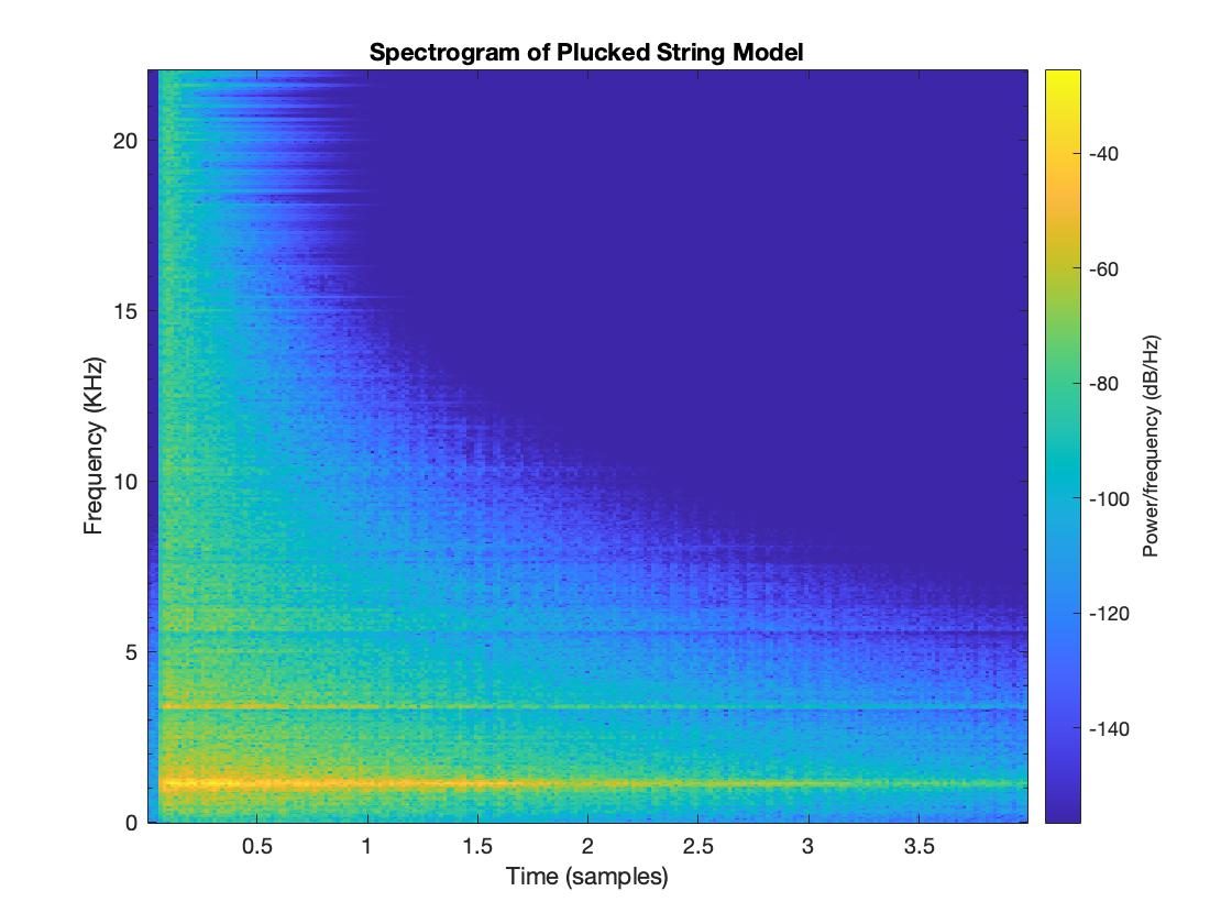
Analysis
The harmonic content of the output changes as the pluck position is moved along the string. This is due to the wave components in each delay line not being equal in distance from the end of their respective line. This means that when the uneven wave components are sampled at output, they contribute different harmonic frequencies. This results in varying timbres as shown above.
Kick - Triangle, Sine, Square
Different timbres of a kick drum can be produced by the model. By increasing the fundamental, other drums could be made.

Changing Pluck Position from Center -> String End
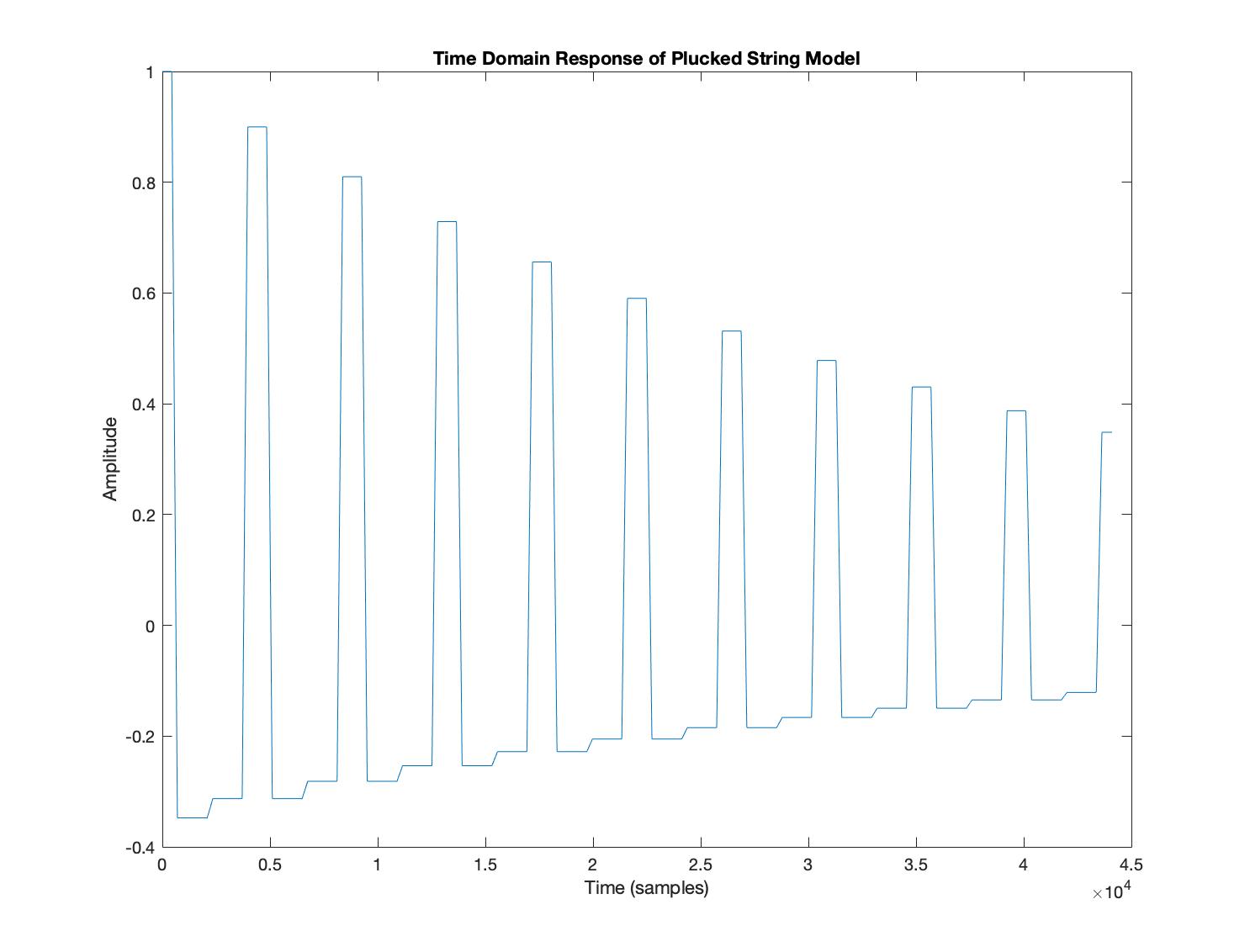
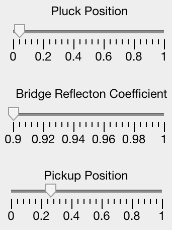
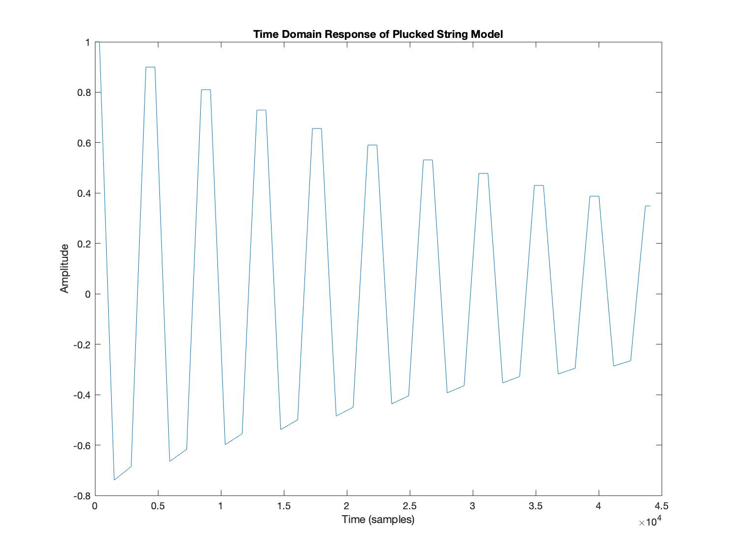
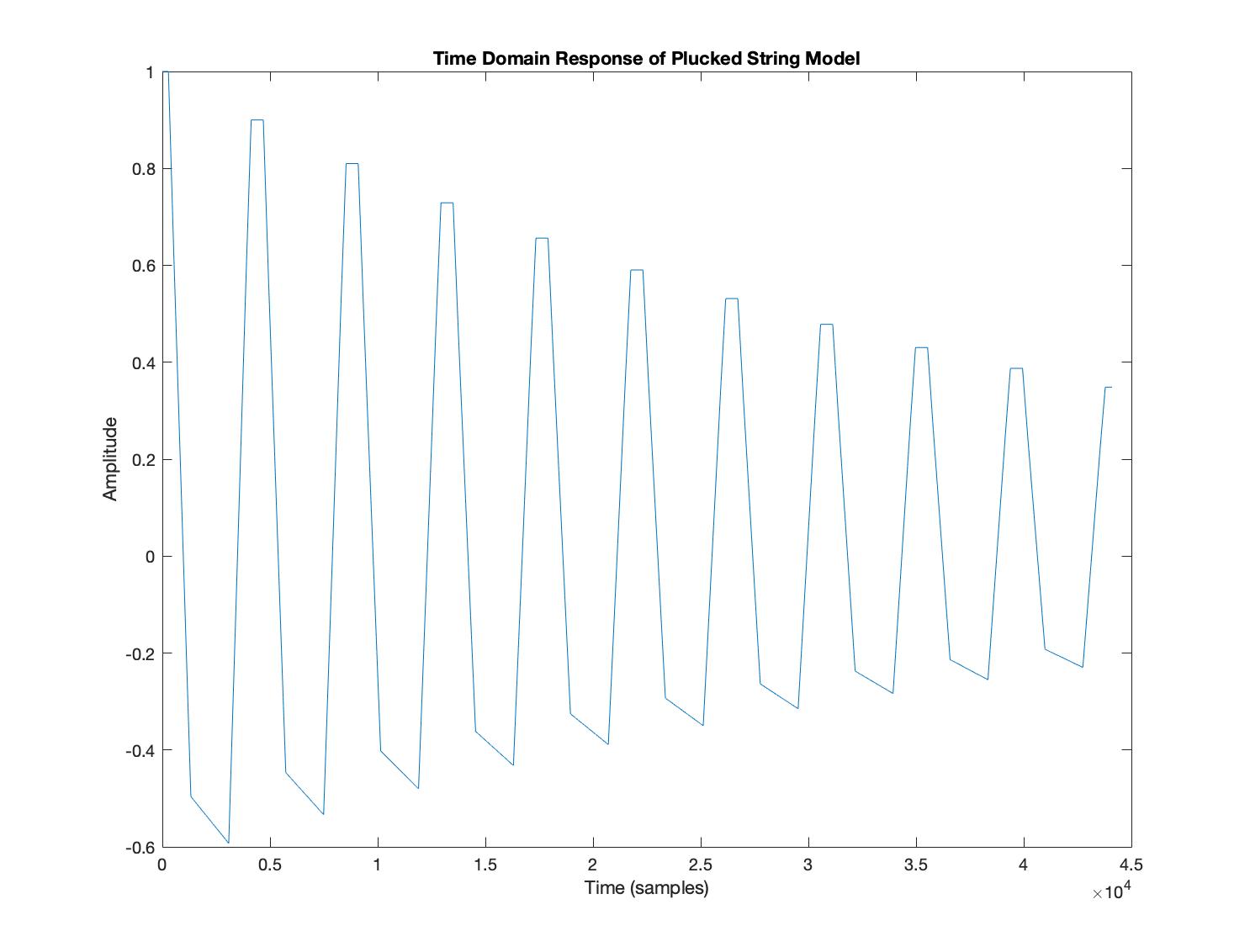
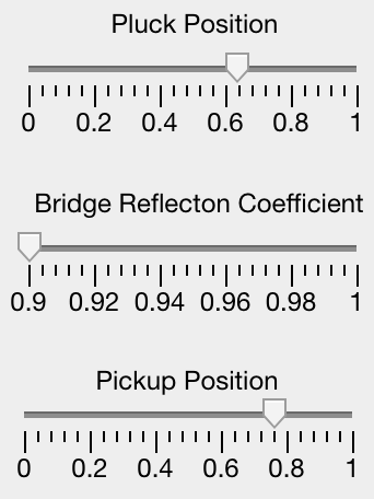
Possible Wave Types
A range of interesting wave shapes can be generated by changing the pluck / pickup positions. Examples of these and the corresponding settings are shown below. The wave shapes are due to the combination of adding odd/even harmonics and sampling in different positions along string delay lines. A frequency of 10hz and low reflection coefficient was used to make the wave shapes more visible in the time domain. By setting the positions at extremes, strange wave types can be formed.


Moorer Reverberator
RT60 of the Room & Hall Models
Due to the code in figure 11, we can see that a larger reverberation was successfully created. The RT60 (time for the reverberation to decay below 60dB) for the Hall model is much greater than the Room. This gives the impression of a larger space.
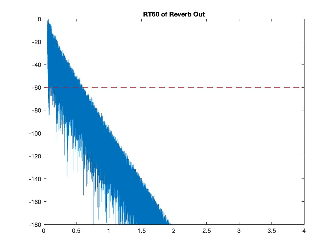
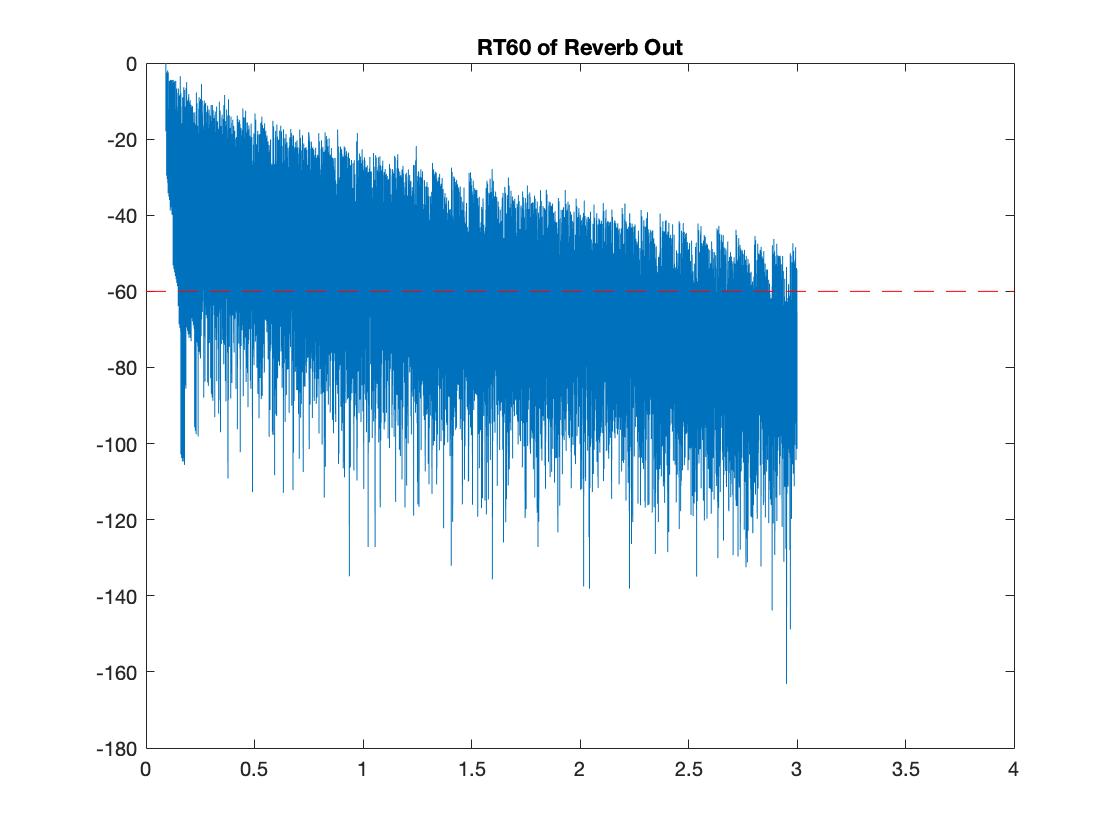
Left: Room, Right: Hall
Comparing Reverberation
A fundamental of 1047 Hz (Approx. C6) was passed through the reverb models. Due to comb filtering and the dense reflections, the spectra becomes more noisey and decay times are greatly increased. You can hear flutter echoes produced in the Hall type as the sound decays. This is due to the delay times set for the filters in the Moorer model. This example sounds similar to a submarine's sonar pulse, due to the chosen pitch and Hall reverb.
Left: Dry, Center: Room, Right: Hall
Future Considerations
- Add additional controls in GUI for Reverb (Delay Settings, Dry/Wet Mix, Gain of Filters, Additional Presets).
- Change the reverberation model. Additional parallel FBCFs with unique delay times can be included to increase the density of the reverb’s late reflections. The diffusion characteristics of the algorithm can be changed by including additional APFs in series.
- Extend Plucked String model to “KS Extended Algorithm” [14].
- Multiple plucks at once.
- Change the shape of the pluck to a square impulse to model a piano.
- Additional Effects (Echo, ADSR Envelope).
Conlcusion
The system implemented here can produce an interesting range of timbres. With future implementations, a rather complex system could be produced which could lead to an advanced ambient tone or texture generator using only physical modelling synthesis.
(Word Count: 1982)